Light always travels through something, be it air, water, glass, or even empty space. The stuff that light travels through is called a medium. If a light ray stays in the same medium, it travels in a straight line 1, but when a light ray travels from one medium to a different medium, it changes direction at the surface between the two media. This is called refraction (Figure 1).
What angle of the light ray causes no bending?
The ray in Figure 1 bends as it passes from air into glass. The amount of bending is described by Snell's Law, named after the Dutch scientist Willebrord Snellius, who developed the formula in 1621. (The amount of bending was first described by Ibn Sahl, a Persian mathematician who lived in Baghdad, around 984CE.)
To describe and use Snell's Law we need some definitions:
The surface normal and the angles of incidence (red) and reflection (green) are shown in Figure 2.
You can click and drag the incoming ray to see how the angles of incidence and refraction change. What can you say, in general terms, about the relationship between the angle of incidence and the angle of refraction?
When a ray of light travels from air into glass (which is what is being simulated in Figure 2), the relation between the angle of incidence and the angle of refraction is
(The notation \( \sin( x ) \) means the sine of the angle \( x \). If you don't know what a sine is, read the trigonometry appendix.) The number 1.52 is called the index of refraction or the refractive index. Using this formula, we can work out the angle of refraction if we know the angle of incidence, or vice versa. For example, if the angle of incidence is \( 45^\circ \), the angle of refraction is \( 28^\circ \), because \( \sin(45)=1.52\times\sin(28) \)
If a ray of light travels from air into water, the relationship between the angle of incidence and the angle of refraction is
The only thing that has changed is the number on the right hand side: \( 1.33 \) is the refractive index for water. Each substance has its own refractive index, and some indices of refraction are given in the table below. There is no simple reason why a substance has a particular index of refraction, but denser substances tend to have higher indices. The index of refraction is never less than \( 1 \), and only rarely more than \( 2 \).
| Medium | Index of Refraction |
|---|---|
| Empty Space | 1.0 |
| Air | 1.0003 |
| Water | 1.333 |
| CR39 | 1.498 |
| Crown Glass | 1.52 |
| Polycarbonate | 1.585 |
| Sapphire Glass | 1.77 |
| Diamond | 2.42 |
The index of refraction for air is \( 1 \) (or nearly so), so Equation (2) for a ray of light passing from air into water can also be written as
That is, each \( \sin( ) \) is multiplied by the refractive index of the medium that the light ray is in, air on the left and water on the right. Generally, for a ray travelling from one medium to another medium, the angles of incidence and refraction are related by the formula
where \( n_{in} \) is the refractive index of the medium that the incident ray is travelling in, and \( n_{out} \) is the refractive index of the medium that the refracted ray is in, as it travels out from the surface. For example, if a ray of light travels from water (refractive index \( 1.33 \) ) to glass (index \( 1.52 \)), equation (3) says
Equation (3) is called Snell's Law.
So far, we've only considered light travelling from a low index medium (e.g. air) to a high-index medium (e.g. glass). In these cases, the angle of refraction is always smaller than the angle of incidence, as you can see from Figure 2. However, when light travels from a high-index medium to a low-index medium, the angle of refraction is always bigger than the angle of incidence (Figure 3 ).
This introduces a new phenomenon. Consider a ray of light travelling from water (index= \( 1.33 \)) into air, with an angle of incidence equal to \( 65^\circ \). Snell's law then says
from which you can work out that \( \sin{(\text{angle of refraction})} = 1.205 \). However, if we try and work out the angle of refraction on a calculator by typing \( \sin^{-1}(1.205) \) we get an error, because the sine of any angle cannot be bigger than \( 1 \). Thus, Snell's Law doesn't work in this case.
What happens instead is that, when the angle of incidence is big enough, the light ray does not escape the denser medium and instead gets reflected. This is called total internal reflection. You can see total internal reflection in action by dragging the incident ray in Figure 3. At high enough angles, the ray is reflected instead of being refracted. The "total" in total internal reflection is because we always get some reflection at a surface; total indicates that all the light is reflected.
The critical angle is the biggest angle of incidence that allows refraction to occur. The biggest possible angle of refraction is \( 90^\circ \), so the critical angle is the angle of incidence when the angle of refraction is \( 90 \); that is
Because \( \sin{(90)}=1 \), this simplifies to
For example, when a ray travels from water (\( n_{in}=1.33 \) ) to air \( (n_{out}=1) \) as in Figure 3, the critical angle is given by
Solving this gives a critical angle of \( \sin^{-1}{(1/1.33)}=48.8^o \). You can confirm this using Figure 3, which simulates light travelling from water into air: angles of incidence less than \( 48.8^\circ \) yield refraction (and some reflection); angles greater than this yield only reflection.
Light changes direction when it passes through a refracting surface. This means we can use refracting surfaces to control the direction of light rays. In Figures 1 to 3 above, the refracting surface has been fixed vertically and we have moved the light ray. In Figure 4, however, the light ray is fixed, but you can change the angle of the refracting surface. By moving the refracting surface, you can redirect the light ray almost anywhere you want to.
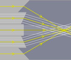
We can bend rays of light in any direction simply by changing the angle between the ray and the refracting surface it hits. Now suppose that we have a set of parallel rays, as in Figure 5 . We can bend all these rays to travel towards a single point (i.e. converge them) if we have a glass surface which has a different orientation for each rays. No flat glass block can do this of course, but if the glass block is faceted, as in Figure 5, and each facet can have a different orientation, then we can make the light rays converge to a point. A lens with this sort of design is called a Fresnel lens (pronounced “fraynel” or, less correctly, “freznel”).
The drawback with Fresnel lenses is that the sharpness of the image is limited by the width of the facets. A distant point has millions of parallel rays leaving it. All of the parallel rays that hit one facet are bent by exactly the same amount, so they all remain parallel, and thus they can't converge on a single point (Figure 6). Despite this problem, Fresnel lenses are still useful when the sharpness of the image doesn't matter too much, and they have the advantage that they can be made very flat and light. Fresnel lenses are thus commonly used when one needs a large lens but wants the lens to be thin and light, e.g. in overhead projectors, or large searchlights, or page-sized magnifiers.
If we want all of the parallel rays from a distant point to converge on a single focus, then each and every ray has to be bent by a different amount. The only way this can be done is by using a smoothly curved surface. To apply Snell’s law to a curved surface, we have to be able to know where the surface normal on a curved surface is (because all the angles in Snell’s law are measured from a surface normal). A surface normal on a flat surface is easy, it’s just at right angles to the surface. A surface normal on a curved surface is a little more subtle. To get the surface normal of a curve, we hold a flat surface against the curve so that it just touches the curve, and draw the normal at right angles to that flat surface ( Figure 7).

Figure 8 below allows you to design a curved surface which focuses light. For simplicity, this figure only lets you adjust the curve at five places (rather like Figure 5 ). If we were really designing a curved surface to focus light, we would have more control over its shape.
Any curved surface could potentially have a very complicated shape, and may be difficult or expensive to make. However, spherical curved surfaces are fairly easy and cheap to manufacture, and for that reason we tend to use spherical surfaces in optics. Another advantage is they are easier to analyze mathematically. Spherical surfaces are quite good at focussing light to a point, although not perfect. Figure 9 allows you to converge or diverge light rays from a single distant point by adjusting the radius of the spherical surface in the middle.
In Figure 9 the parallel rays can be made to converge to a single point (or appear to diverge from a point). That is, the spherical surface has a power. The power depends on the radius of the sphere and the refractive indices. The formula for the power of a spherical surface is
where \( r \) is the radius of the surface in metres, and \( n_{in} \) and \( n_{out} \) are the refractive indices for the incident and refracted rays.
In Figure 9, \( n_{in} \) is the refractive index to the left of the spherical surface; \( n_{out} \) is the refractive index to the right of the surface; and \( r \) is the distance measured from the surface to the centre of the sphere. The distance \( r \) follows the sign convention, so in Figure 9, radii pointing to the right are positive, and radii pointing to the left are negative, because the light in the figure travels from right to left.
Equation (4) gives rise to four different situations, depending on whether \( \ n_{out} - n_{in} \) is positive or negative, and whether \( r \) is positive or negative. These four situations are shown in Figure 10.

The two surfaces on the left are convex surfaces and the two surfaces on the right are concave.
The thin lens equation (given in Chapter 1) is
There are no refractive indices in this equation because the vergences \( V_{in} \) and \( V_{out} \) are for light in air, which has a refractive index of \( 1 \). If we put in the refractive indices for air, the thin lens equation would look like
There is a similar formula which is used to work out the change in vergence as light travels across a spherical surface, called the the paraxial equation:
In this equation \( n_{in} \) and \( n_{out} \) are the refractive indices to the left and right of the surface (assuming the light travels from left to right as in Figure 6) and \( F_{surface} \) is the surface power, given by Equation (4). We can use the paraxial equation in the same way as we used the thin lens equation, as shown in the example below.
Let's use the paraxial equation to work out where a refracting surface forms an image. An object in air has been placed 0.8m to the left of a refracting surface made of glass. The glass surface has a radius of 25cm, and the centre of the surface is to the right. The glass has a refractive index of 1.5 and, as always, air has a refractive index of 1. Where does the image form?
As always, it is a good idea to draw a sketch of the situation. Here is one:
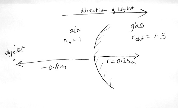
To figure out which way the surface is curved, draw the radius line in first, then the surface bends in the same direction as the radius is pointing.
The first thing we need to do is work out the surface power. This is \( (n_{out}-n_{in})/r = ( 1.5 - 1 )/0.25 = + 2D \).
The vergence of the light hitting the surface is \( 1/(-0.8) = - 1.25D \) Substituting the quantities that we know into the paraxial equation, we have
Thus \( V_{out} = 0.75/1.5 = 0.5 \). The image therefore forms at \( 1/V_{out}=2{\text{m}} \) to the right of the surface.
The reason this equation is called the paraxial equation is because it is only valid for light rays that are near to ( par-) the optic axis (-axial) of a refracting surface. The optic axis of a refracting surface or lens is the axis of rotational symmetry. A paraxial ray has to do two things:
These two rules ensure that the angle of incidenceof the ray is small. Figure 11 shows examples of two paraxial rays (in green) and two non-paraxial rays (in red). The paraxial equation applies to bundles of converging or diverging paraxial rays; if the rays aren't paraxial, the paraxial equation becomes inaccurate. Luckily, we will mostly be dealing with paraxial rays in optics.

The image focal length and object focal length can be defined exactly as they were for a lens. The image focal length is the distance from surface to image when parallel light ( \( V_{in}=0 \)) strikes the surface, and can be worked out from the paraxial equation as follows:
| Step | Statement | Reason |
|---|---|---|
| 1 | \( n_{in}V_{in}+F_{surface}=n_{out}V_{out} \) | The paraxial equation |
| 2 | \( F_{surface}=n_{out}V_{out} \) | Set \( V_{in}=0 \) |
| 3 | \[ \frac{F_{surface}}{n_{out}} = V_{out}
\] |
Divide both sides by \( n_{out} \) |
| 4 | \[ \frac{n_{out}}{F_{surface}} = \frac{1}{V_{out}}
\] |
\( 1/V_{out} \) is the image distance, so take the reciprocal of both sides |
| 5 | \[ \frac{n_{out}}{F_{surface}} =\text{image distance}
\] |
\( 1/V_{out} \) is the image distance |
| 6 | \[ \frac{n_{out}}{F_{surface}} =\text{focal length}
\] |
The image distance is the focal length when \( V_{in}=0 \) |
Thus, the image focal length \( f_{img} \) is
The object focal length is the distance from the surface to an object which causes parallel light to leave the surface (\( V_{out}=0 \)). We can show that the object focal length is
The difference between these focal lengths and the ones given in Chapter 1 is the involvement of the refractive indices to the left and right of the surface. It means that the two focal lengths for a refracting surface are different, unlike the two focal lengths of a thin lens which are the same.
If you've ever looked into a swimming pool, you might have noticed that it appears shallower than it really is. That is, the apparent depth of the pool is less than the true depth. This is a consequence of the paraxial equation that was introduced just above.
Take a flat surface, with a high refractive index to the left, and air to the right, as in Figure 12. The surface power of the flat surface is simply zero. There is an object somewhere to the left of the flat surface, in the higher index medium. By the time the rays of light from the object strike the flat surface, they have some vergence \( V_{in} \). According to the paraxial equation,
But since \( F_{surface} = 0 \), this becomes
or, rearranging,
so the vergence has changed because of the different refractive indices. However, unlike a lens which adds vergence, the flat refracting surface has multiplied the vergence. In the case of Figure 11, the light leaving the surface is diverging more than the light entering it, and this is always the case when light goes from a more dense to a less dense medium.
If the increase in divergence reminds you a little of a negative lens, it should, because the divergent light leaving the surface creates a virtual image of the object which happens to be closer than the object. The distance from the surface to the virtual image is just \( 1/V_{out} \). If we looked at the diverging light leaving the surface, we would see the object at the location of the virtual image, and not at its true location.
Let's figure out how deep a \( 2 \text{m} \) pool appears to be.
So if you're \( 1.75\text{m} \) tall, the pool looks shallow enough to stand in, but in fact you'll go over your head if you try.
Now that you've read this chapter, you can do a self-test
Although we call the law of refraction "Snell's Law", it was actually discovered by Persian mathematician Ibn Sahl who lived in Baghdad from roughly 940-1000 CE (CE means Current Era and is the same as AD). Here we're going to have a quick look at this.
The figure below is a short slideshow setting up Ibn Sahl's law. Click through the slideshow and read all the captions carefully, then continue.

(The curved scribbles to the right are part of another diagram, and we don't care about them.) In the next few slides we will see how this is the same as Snell's Law.
Click the arrow on the right to continue.

Click the right arrow to continue.

Click the right arrow to continue.

Click the right arrow to continue.

Click the right arrow to continue.

One another line has been added to the drawing. The length of this line is O, and it's been named O because it's opposite the two angles \( \theta_{in} \) and \( \theta_{out} \) . \( L_1 \) and \( L_2 \) are hypotenueses of two triangles.
Now read on:
In Figure 13(f), we have two angles \( \theta_{in} \) and \( \theta_{out} \), and three lines with lengths \( L_1 \), \( L_2 \) and \( \mathbf{O} \). From what we have in Figure 13(f), and Ibn Sahl's Law, we can get Snell's Law, as follows:
| Step | Statement | Reason |
|---|---|---|
| 1 | \( \dfrac{L_1}{L_2} = \dfrac{n_{out}}{n_{in}} \) | Ibn Sahl's Law from Figure 13(a) |
| 2 | \( \dfrac{n_{in}}{L_2} = \dfrac{n_{out}}{L_1} \) | Cross multiply |
| 3 | \( \sin{\theta_{in}} = \dfrac{\mathbf{O}}{L_2} \) | From Figure 13(f), sides of triangle holding \( \theta_{in} \) |
| 4 | \( L_2 = \dfrac{\mathbf{O}}{\sin{\theta_{in}}} \) | Cross multiply statement 3 |
| 5 | \( \sin{\theta_{out}} = \dfrac{\mathbf{O}}{L_1} \) | From Figure 13(f), sides of triangle holding \( \theta_{out} \) |
| 6 | \( L_1 = \dfrac{\mathbf{O}}{\sin{\theta_{out}}} \) | Cross multiply statement 5 |
| 7 | \( \dfrac{n_{in}}{\mathbf{O}/\sin{\theta_{in}}} = \dfrac{n_{out}}{L_1} \) | Substitute statement 4 for \( L_2 \) |
| 8 | \( \dfrac{n_{in}}{\mathbf{O}/\sin{\theta_{in}}} = \dfrac{n_{out}}{\mathbf{O}/\sin{\theta_{out}}} \) | Substitute statement 6 for \( L_1 \) |
| 9 | \( \dfrac{n_{in}}{1/\sin{\theta_{in}}} = \dfrac{n_{out}}{1/\sin{\theta_{out}}} \) | Multiply both sides by mathbf{O} |
| 10 | \( \dfrac{n_{in}\sin{\theta_{in}}}{1} = \dfrac{n_{out}}{1/\sin{\theta_{out}}} \) | Multiply top and bottom of left hand side by \( \sin{\theta_{in}} \) |
| 11 | \( \dfrac{n_{in}\sin{\theta_{in}}}{1} = \dfrac{n_{out}\sin{\theta_{out}}}{1} \) | Multiply top and bottom of right hand side by \( \sin{\theta_{out}} \) |
| 12 | \( n_{in}\sin{\theta_{in}} = n_{out}\sin{\theta_{out}} \) | Simplify to get Snell's Law |
Thus Snell's Law can be derived from Ibn Sahl's law (and vice versa, of course).
Who knows. Racism perhaps? There's a good chance Willebrord Snell knew the work of some of the Persian mathematicians from Ibn Sahl's time, but it's hard to prove he read Ibn Sahl's book. Even if he had, he might not have bothered crediting Ibn Sahl (academic credit was even less common back then than it is now.)
The only thing in favour of calling it Snell's Law rather than Ibn Sahl's Law is that Snell provided us with a formula we could use for calculation, but Ibn Sahl didn't. He could have, easily, because trigonometry was well-known in his time, and he would have been able to do the steps I took above, but he chose not to. We may never know why, but if I were to guess, I'd say it was because Ibn Sahl, like most mathematicians of his time, had enormous respect for ancient Greek geometry, and the Greek style of geometry did not seem much interested in formulas.