Light is made of things called photons, which travel in straight lines until they hit an object. When they do, one of three things can happen:
the photon gets absorbed, and heats the object a little bit, or
if the object is transparent, the photon goes through the object, possibly changing direction, or
the photon bounces off the object. That is, it is reflected. If the object isn't shiny, the photons hitting it will bounce off in random directions.
The third thing is what interests us here.
Two light rays (out of many) are shown leaving a light source at the top of
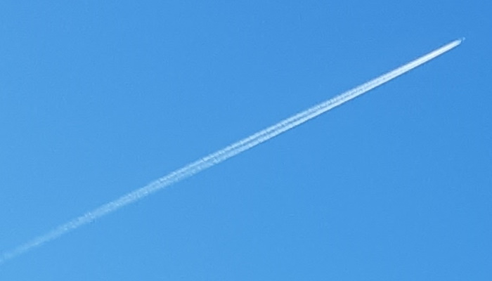
Figure 1(a). A light ray is a line that shows where one or more photons of light has travelled. This is something like an aeroplane's vapour trail, with the photon as the plane; see
Figure 1(b). Each of these two rays in fact show the path traced by many photons. When these photons hit the object, they bounce off in different, random, directions; each photon then has its own ray. The reflected rays spread out (or
diverge) in a broad fan from each point.
Figure 1(a). A light source at the top of the picture sends out many rays of light. Two of them are shown hitting an object. Each ray leaving the light source consists of many photons, and when they hit the object, the photons reflect off in random directions to form fans of diverging rays.
(Click the arrow to the right to see the next picture.)
Figure 1(b). The rays in Figure 1(a) show where a photon has travelled, much like a vapour trail in the sky shows where the plane that made it
has been. (Click the arrow to the right to see the next picture.)
Figure 1(c). Here, the reflected light is being caught by a screen (shown as a grey line to the right). The light hitting the screen tells us that there is something in front of the screen that is reflecting light, but not what or where it is, because light from different points on the object is all smeared together on the screen.
For example, the points A and B on the screen both catch light from the top and bottom points on the object, so we can't distinguish the top of the object from the bottom.
Figure 1(d). Here, a barrier with a tiny hole (called a pinhole) is placed between the object and the screen. The hole is so small that only one ray from each point in the object is allowed through.
Now the light hitting point A comes from one direction, and the light hitting point B comes from a different direction, so we now know something about where the light is coming from. This is what we need to make an
image. One problem, however, is that the pinhole has blocked most of the light, so the image is quite dim.
Figure 1(e). A lens (in purple) catches lots of divergent light coming from a point on an object and converges it to a point on the screen. It does this, simultaneously, for all the points on the object. The light converging on point A or point B all comes from the same place, so again we know where the light is coming from on the screen. This image is much brighter than the pinhole image, because each point (A or B) receives many rays of light.
These reflected rays carry information about the objects they have bounced off of. If we catch those reflected rays, we might be able to figure out something about the world in front of us: where the object is, its shape, or even what it is.
However, if we try to capture and use the light reflecting off the apple by putting in a flat screen to absorb the light, as in
Figure 1(c), we only get an overall idea of how much reflected light there is. To make sense of the world, we also need to know
where the light is coming from. One way to do this is to use a "pinhole", which is an opaque barrier with a tiny (i.e. pin-sized) hole in it. The hole is so small that effectively only one ray of light coming from any point on the object can get through it. When a ray of light then hits a screen (
Figure 1(d)) we know where the light is coming from, since only light coming through the pinhole in a certain direction can hit the screen at that point.
This is an image: a pattern of light on a flat screen, where we know which direction the light is coming from at all points in the pattern.
The drawback with pinholes is that very little light gets through the hole, so the image is very dim. If we could somehow gather more of the light rays diverging from a single point, and
converge them back to a point, we could make the image much brighter. This is what a
lens does (Figure 1(e)). Because a lens captures a lot of rays, each point on the image is brighter than using the pinhole so the whole image is brighter. Just like a pinhole image, a lens image is flipped upside down and left-to-right.
This is what lenses do: they create images by capturing divergent light from points on an object, and converge them to make points on an image.
In optics, one thing we are particularly interested in is how far the image is from the lens, and how that depends on the object's distance and the lens itself. Then we can put the flat screen at the right place to get an image of the things in front of us.
That's what we are going to describe in this chapter: how to figure out where a lens forms an image. To do that, we first need to get more precise about what is meant by converging light and diverging light.
Convergence
Converging light is light that is coming together, eventually to a single point, like the light leaving the lens in
Figure 1(e). You would expect a very convergent bundle of rays leaving a lens to come together quickly, while a less convergent bundle of rays should take longer to come together (see
Figure 2(a) and (b)).
Figure 2(a). A bundle of rays leaving a lens with high convergence will come to a point quickly, so the distance from the lens to the point where all the rays converge is small.
Figure 2(b). A bundle of rays leaving a lens with low convergence will come to a point slowly, so the distance from the lens to the point where all the rays converge is large.
Intuitively, then, convergence is the opposite of the distance it takes the rays to come together to a point: that is,
more convergence means less distance.
We can define the convergence of light leaving a lens by a formula:
\[\text{convergence} = \frac{1}{\text{distance from lens to point where the light converges}}\tag{1}\]
Since the point where the light converges is where the image forms (as in
Figure 1(d)), we can also think of convergence as
\[\text{convergence} = \frac{1}{\text{distance from lens to image}}\tag{2}\]
In most optical calculations, distances are measured in metres
, so the units of convergence are \( \text{metres}^{-1} \)
. This unit of convergence is given the name dioptre, pronounced di-op-ter
, and abbreviated \( \text{D} \). For example, if a bundle of rays leaving a lens comes together to a point at
\( 0.5\text{m} \) away from the lens, then the convergence of the light leaving the lens is, according to Equation (1),
\( 1/0.5 = 2 \) dioptres, or \( 2\text{D}
\).
Equation (2) can be rearranged as:
\[\text{distance from lens to image} = \frac{1}{\text{convergence}}\tag{3}\]
So if we know that a bundle of light rays leaving a lens has a convergence of say
\( 5\text{D} \), then from this formula we know that they will come together to form an image point at
\( 1/5 = 0.2 \) metres away from the lens. If the light leaving the lens has a convergence of
\( 10\text{D} \), it will come together
\( 1/10 = 0.1 \) metres from the lens. And so on.
So if we know the convergence of the light leaving the lens, we can work out where the image appears: it's where all the bundles of converging light come together to a point.
Divergence
Light rays diverge if they are spreading apart. The divergence of a bundle of rays, when they hit a lens, is related to how much they are spreading apart when they hit it.
Figure 3(a) and (b) shows a bundle of rays diverging from a point and hitting a lens.
Figure 3(a). A bundle of divergent rays starting a short distance from a lens will have high divergence when they strike it.
Figure 3(b). A bundle of divergent rays starting a long way from a lens will have low divergence when they finally strike it.
When the rays start from a place which is quite close to the lens, they are highly divergent when they hit it. That is, the the rays at the top and bottom of the lens are travelling in very different directions. Conversely, when the rays start from a distant point, they are not very divergent when they hit the lens, and the the rays at the top and bottom of the lens are travelling in more similar directions. So, like convergence, there is an inverse relationship between distance and divergence:
more divergence means less distance.
The divergence of a bundle of light rays coming from some point and hitting a lens is defined by the formula:
\[\text{divergence} = \frac{1}{\text{distance from lens to the point where the rays start}}\tag{4}\]
Since the point where the rays spread out from is usually an object, we can also write
\[\text{divergence} = \frac{1}{\text{distance from lens to the object}}\tag{5}\]
As before, the distance is measured in metres and the divergence is given in dioptres.
The Sign Convention
Divergence is in some sense the opposite of convergence, and it would be good to have some way of showing this. In optics, we do this by making divergence a
negative number. For example, if a bundle of rays is diverging from an object that is
\( 125\text{mm} \) (or \( 0.125\text{m}
\)) away from a lens, the divergence of the light when it hits the lens is
\( 1/0.125 = 8\text{D} \). Because divergence is negative, we stick a minus sign in front of it, to get
\( -8\text{D} \). Any time you see a negative value for dioptres, you know you're dealing with divergent light.
The divergence Equation (5) can be rearranged as
\[\text{distance from lens to the object} = \frac{1}{\text{divergence}}\tag{5}\]
For example, suppose some light has a divergence of \( -4\text{D}
\) when it hits a lens. The formula says that the distance from the lens to the point is then
\( 1/(-4) = -0.25\text{m} \). That is, the distance from the lens to the object is
negative.
But what on earth is a negative distance?
A negative distance is an example of what is called the sign convention
, summarized in Figure 4. In optical calculations, some distances are deemed to be positive and some are deemed to be negative. The sign convention can be set down in a few rules:
Figure 4. The sign convention. Light travels from the object through the lens to the image. This is
left-to-right or rightwards. The direction going from lens to object is opposite the direction of light (i.e. is leftwards), so it is a negative (-) distance. The direction going from lens to image is the same as the direction of light (i.e. is rightwards), so it is a positive (+) distance.
Click the arrow on the right to see the sign convention for light travelling from right-to-left.
Figure 4. The sign convention. Light travels from the object through the lens to the image. This is
right-to-left or leftwards. The direction going from lens to object is opposite the direction of light (i.e. is leftwards), so it is a negative (-) distance. The direction going from lens to image is the same as the direction of light (i.e. is rightwards), so it is a positive (+) distance.
Click the arrow on the left to see the sign convention for light travelling from left-to-right.
All distances are measured from the lens.
Each measured distance has a direction, which is the direction you'd have to move to go from the lens to your destination. In
Figure 4(a), the distance from the lens to the apple is leftwards, because if we started at the lens, we'd have to move left to get to the apple. The distance from the lens to the image screen is rightwards, because if we started at the lens, we'd have to move right to get to the screen.
A distance whose direction is the same as the direction of the light is positive. In
Figure 4(a), the distance to the image is the same direction as the direction of the light, so it's positive.
A distance whose direction is the opposite of the direction of the light is negative. In
Figure 4(a), the distance to the apple is opposite the direction of the light (rightward), so it's negative.
The sign convention can be tricky, because we're not used to distances having signs, but it gets easier with practice. But if it's so tricky, why do we use the sign convention in optics? One reason is because we don't then need separate definitions for divergence or convergence any more; we only need one definition, which we will call
vergence:
\[
\text{vergence} = \frac{1}{\text{distance from lens to the object }\textbf{or}\text{ image}}\tag{7}
\]
The sign of the vergence tells you whether the light is converging or diverging: negative vergence means diverging light, and positive vergence means converging light.
If we know the convergence or divergence of the light hitting or leaving the lens, we can work out the distance to the image or object by
\[\text{distance from lens to the object or image} = \frac{1}{\text{vergence}}\tag{8}\]
The distance may be either positive or negative, and that tells us which direction we should travel, starting from the lens, to find the object or the image. If it's a positive distance, we travel in the same direction as the light, and if it's a negative distance, opposite the direction of the light.
The Thin Lens Equation.
Figure 5 shows a lens forming a sharp image of a single point object, like one of the bundles of rays in
Figure 1(d). Like many images in this book, it is interactive: you can drag parts of it around and see what happens. If you tap the little hand icon off to the right, it will illuminate the parts of the figure that you can move.
In Figure 5, light diverges from a point on the left and hits the lens. The lens changes this to convergent light, and this converges to a single point, which is the image. In
Figure 5, the object is \( 1\text{m} \)
away from the lens, to the left; and the light converges to a point
\( 0.33\text{m} \) away from the lens, to the right.
Usually, the object and image are composed of many points, as in
Figure 1(d), but if we can work out what happens to one point, we can work out what happens to all of them.
Figure 5. An object point is \( 1\text{m} \)
to the left of the lens, and the image point forms \( 0.333\text{m}
\) to the right of the lens. The lens is drawn as a double-headed arrow, which is a standard symbol for a converging lens. Small arrowheads on the light rays show the direction the light is travelling.
You can grab and move the light to different distances and see what happens to the distance to the image. Note that if you get the object too close to the lens, the image distance gets very large, until at some point the light leaving the lens doesn't converge any more.
The continue rays checkbox is there because unless we put in something to stop the light, it will keep going. Click the box to see what happens.
Let's work out the vergences of the light entering the lens and leaving the lens.
The light in the diagram is travelling from left to right, as shown by the little arrows on the light rays.
The object is to the left of the lens (opposite the direction of light), so from the sign convention the distance is negative. Thus, the distance from lens to object is
\( -1\text{m} \), and the vergence of the light when it hits the lens is just
\( 1/(-1) = -1\text{D} \).
The image is to the right of the lens, so it is a positive distance in this case. The light leaving the lens converges
\( 0.333\text{m} \) away from the lens, so the vergence of the light as it leaves the lens must be
\( 1/0.333 = 3\text{D} \).
What happened to the vergence of the light as it passed through the lens? It hit the lens with a vergence of
\( -1\text{D} \) and left the lens with a vergence of
\( 3\text{D} \). So the lens had the effect of adding \(
4\text{D} \) of convergence to the light that passed through the lens (since
\( -1\text{D}+4=3\text{D} \)).
Because Figure 5 is interactive, you can try a few other distances by dragging around the point where the light begins. Here are some examples in a table, with vergence calculations:
Distance from lens to object
Distance from lens to image
Vergence of light entering lens
Vergence of light leaving lens
Change in vergence (leaving-entering)
\( -1\text{m} \)
\( 0.333\text{m} \)
\( -1\text{D} \)
\( 3\text{D} \)
\( 3-(-1)=4\text{D} \)
\( -0.883\text{m} \)
\( 0.349\text{m} \)
\( -1.13\text{D} \)
\( 2.87\text{D} \)
\( 2.87-(-1.13)=4\text{D} \)
\( -1.249\text{m} \)
\( 0.313\text{m} \)
\( -0.8\text{D} \)
\( 3.19\text{D} \)
\( 3.19-(-0.8)=3.99\text{D} \)
The last column (the change in vergence as the light goes through the lens) is always close to
\( 4\text{D} \) and, if it wasn't for rounding, would be exactly
\( 4\text{D} \). So this lens always adds
\( 4\text{D} \) of convergence to the light as it passes through it.
This is how lenses work: they change the vergence of the light passing through them by a fixed amount.
The amount that a lens changes the vergence of light is called the lens
power. The lens in Figure 5 has a power of
\( 4\text{D} \), because it always changes the vergence of the light passing through it by that amount. (Note that when we write down positive powers, we normally put a plus sign in front of them, so the power of this lens is written as
\( +4\text{D} \)).
The Equation Itself.
All the calculations we've been doing can be summarized in a really simple equation called the
thin lens equation:1
This can be abbreviated to save writing so much. The abbreviation we'll use is
\[V_{in} + F = V_{out}\tag{8}\]
In this equation,
\( V_{in} \) means the Vergence of the light going
in to, or hitting, the lens. Typically, \( V_{in} \)
is the same as \( 1/\text{(distance from lens to object)} \)
, which is negative.
\( F \) is the Focal power of the lens.
\( V_{out} \) means the Vergence of the light coming
out of, or leaving, the lens. \( V_{out} \)
is the same as \( 1/\text{(distance from lens to image)} \)
. That means that the image forms at a distance of \( 1/V_{out}
\), from Equation (7).
Almost all optics involving lenses can be analysed and understood using the thin lens equation, so it's really, really important.
Basic Optical Calculations.
The best way to see how to use the thin lens equation is to look at a few examples:
Example 1
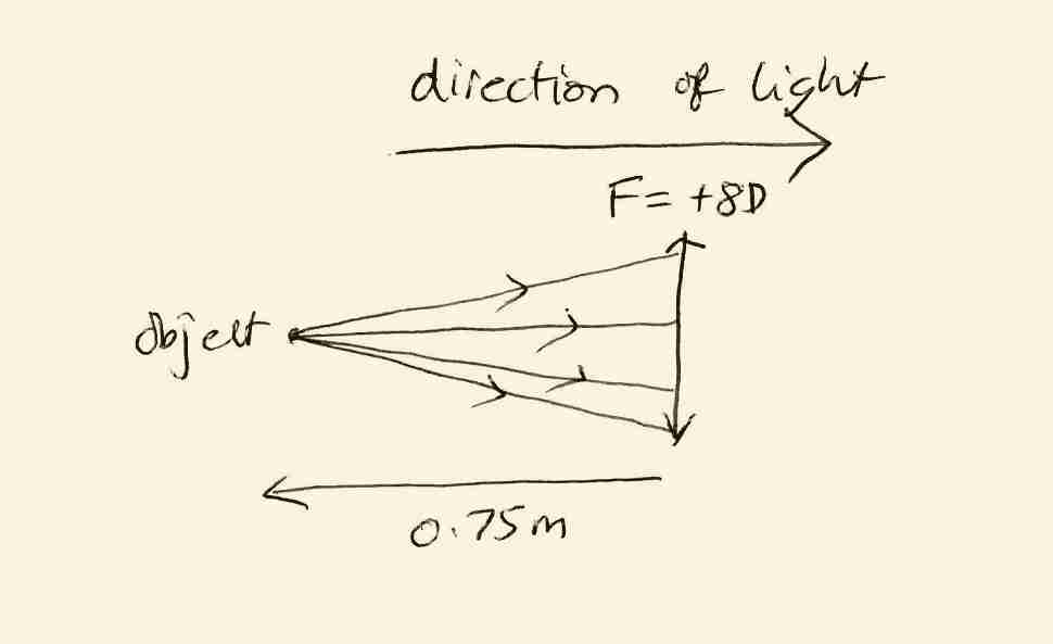
An object is placed \( 75\text{cm} \) to the left of a lens which has a power of
\( +8\text{D} \). Where does the image form?
Answer
Until you get used to these calculations (and often even then) it is a good idea to start with a sketch to makes it clear where everything is, and what sign the distances are. This is the sketch I drew for this example:
The sketch includes arrows on the rays of light to show which direction they are travelling and arrows at the end of every distance to show which direction you move when you're measuring the distance. (Note that the distance has been changed to metres, which you have to do in optical calculations.) It also includes the direction of the light at the top. It looks a lot like Figure 5
.
First, we need to figure out whether the object distance is positive or negative. The light is travelling to the right in the sketch. The object is to the left of the lens. That's opposite the light direction, so it's a negative distance,
\( -0.75\text{m} \).
Next we have to figure out the vergence of the light coming from the object. The vergence
\( V_{in} \) of the light entering the lens is one over the distance to the object:
\( V_{in} = 1/(-0.75) = - 1.33333\text{D} \) (rounded).
The focal power of the lens is \( F=+8\text{D} \), so the vergence of the light leaving the lens is
\( V_{out}=V_{in} + F = -1.33333 + 8 = +6.67\text{D} \), according to the Thin Lens equation. This is positive so the light leaving the lens is converging.
Finally, we convert the vergence \( V_{out} \) into the distance to the image. This is one over the vergence, so the light converges to a point which is
\( 1/6.67 = 0.15\text{m} \) from the lens. Because it is a positive distance, the point of convergence (and hence the image) is to the right of the lens.
Our conclusion: the image forms \( 0.15\text{m} \) to the right of the lens.
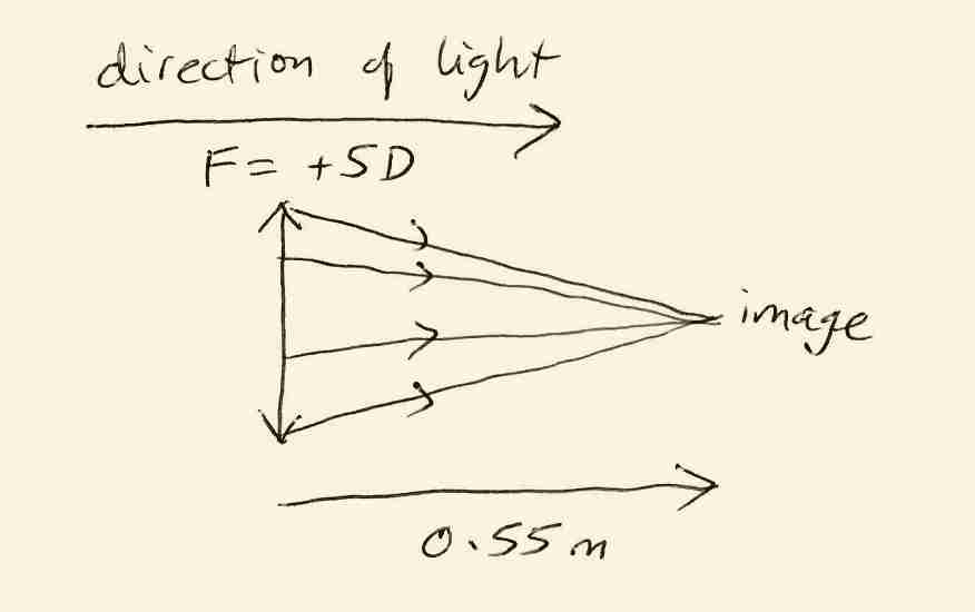
Example 2
A lens with a power of \( +5\text{D} \) forms a sharp image
\( 550\text{mm} \) to its right. Where was the object?
Answer
The sketch for this problem:
Here, we know that the rays leave the lens and converge to a point where the image is. I haven't drawn the rays entering the lens because I don't yet know where they come from.
The distance to the image is positive because it's to the right of the lens (same direction as the light). Thus the vergence of the light leaving the lens
\( V_{out} \) must be \( 1/0.55 = 1.82\text{D}
\).
The thin lens equation is \( V_{in} + F = V_{out} \). Since
\( F \) is \( +5\text{D} \) and
\( V_{out}=1.82\text{D} \), the equation becomes
\( V_{in}+5=1.82 \). Solve this equation by subtracting
\( 5 \) from both sides to get \( V_{in} = -3.18\text{D}
\).
The distance to the object is \( 1/V_{in} \), so the object is at
\( 1/(-3.18) = -0.314 \) metres from the lens. A negative distance means the object is to the left of the lens.
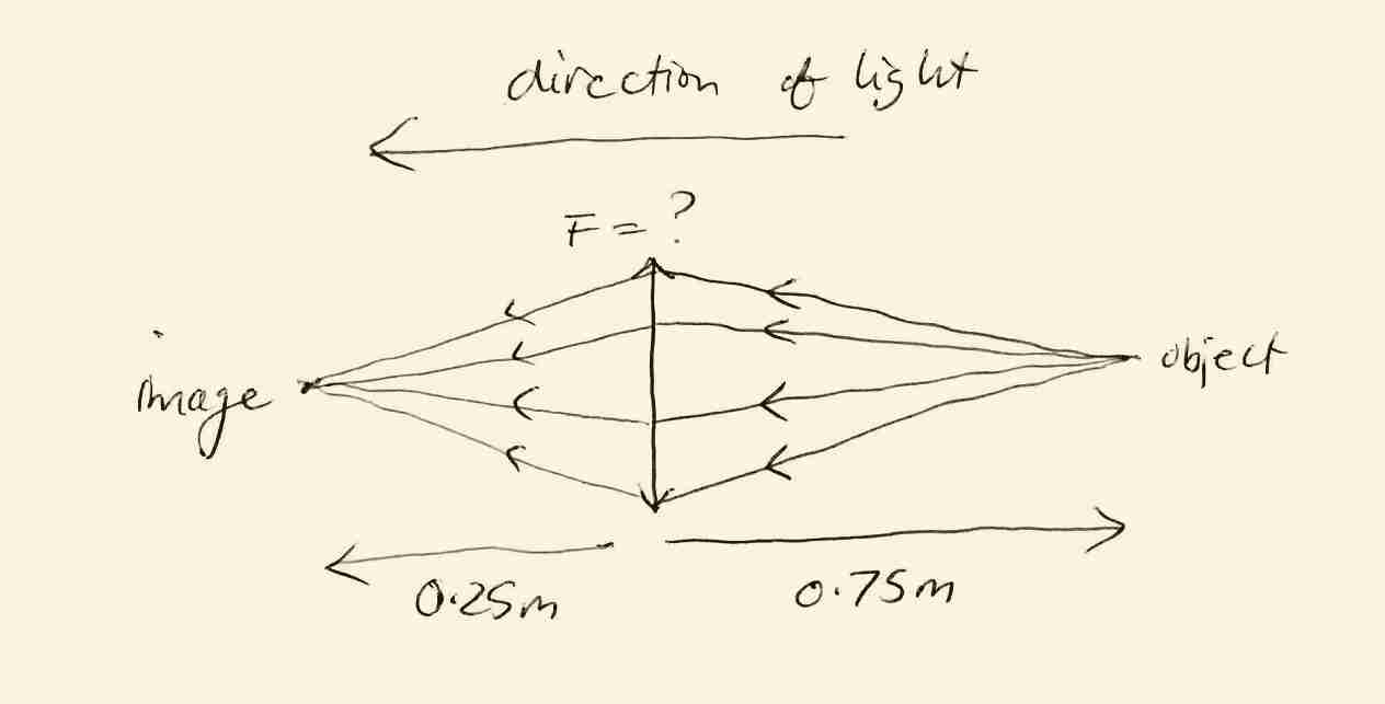
Example 3
An object is placed \( 75\text{cm} \) to the
right of a lens, and a sharp image forms \( 25\text{cm}
\) to the left of the lens. What is the power of the lens?
Answer
The sketch for this problem:
This time, the he light is travelling leftwards from the object through the lens to the image. But the sign convention lets us deal with it pretty easily. The object is to the right of the lens, which is opposite the direction of the light, so it's a negative distance (again). The image is to the left of the lens, so it's a positive distance.
The vergence entering the lens is one over the distance to the object,
\( V_{in}=1/(-0.75)=-1.33\text{D} \)
The vergence leaving the lens is one over the distance to the image,
\( V_{out}=1/0.25=4\text{D} \)
The thin lens equation is \( V_{in}+F=V_{out} \). Putting in the values we know gives us
\( -1.33+F=4 \). Adding 1.33 to both sides gives
\( F=+5.33\text{D} \), which is the answer.
Note that vergences have been rounded to 2 decimal places here, but full accuracy has been used in the calculations. You should use the full accuracy offered by your calculator when you do these calculations.
Focal Length
So far, our main concern has been with light that is convergent or divergent. However, some interesting things happen when light is neither. A bundle of light rays that is neither divergent nor convergent has rays which aren't spreading apart or coming together. The only way that can happen is if the rays of light are parallel.
The vergence of parallel light is zero. Why? Because parallel rays aren't diverging, their vergence can't be negative. Because parallel rays aren't converging, their vergence can't be positive either. The only number that isn't positive and isn't negative is zero, so parallel light has a vergence of zero.
Light coming from very distant objects is almost parallel. For example, the horizon is about
\( 5000\text{m} \) away. Light from the horizon entering a lens has a divergence of
\( V_{in}=1/(-5000) = -0.002\text{D} \). That's pretty close to zero (although still negative). The sun is about 150 billion metres away from us, so sunlight entering a lens on earth has a vergence of about
\( V_{in}=1/(-150,000,000,000)=-0.000000000007\text{D} \)
. That's very close to zero.
What happens when parallel light (say from a distant object) enters a lens? We can use the thin lens equation to find out:
Step
Statement
Reason
1
\( V_{in}+F=V_{out} \)
The thin lens equation
2
\( F=V_{out} \)
Set \( V_{in}=0 \) because the incoming light is parallel
3
\( 1/F=1/V_{out} \)
Take the reciprocal of both sides
4
\( 1/F=\text{image distance} \)
\( 1/V_{out} \) is distance to image
So when \( V_{in}=0 \), the image distance is equal to
\( 1/F \). This distance is called the Focal Length
, because it is directly related to the focal power \(
F \). If you need it, the usual symbol for focal length is
\( f \), and so \( f=1/F \), and vice versa,
\( F=1/f \). The point where the rays converge is called the Focal Point
(see Figure 6 ).
You can use Figure 6 to explore the relationship between lens power
\( F \) and focal length \( f \)
. Notice that low powered lenses have a long focal length, and high powered lenses have a short focal length.
Figure 6(a). When the object is very far away, rays of light entering the lens are parallel, with a vergence
\( V_{in} \) equal to zero. In this case, the distance to the image is called the Focal Length, and light converges on a focal point. The power of the lens is
\( 10\text{D} \) (at the top of the picture), so
\( V_{out}=10 \), and the distance to the image is \( 1/10 = 0.1\text{m}
\). When \( V_{in}=0 \), as here and in Figures 6(b)-6(e), the image is called the focal point.
Figure 6(b). The power of the lens is \( 5\text{D}
\), so \( V_{out}=5 \), and the distance to the focal point is
\( 1/5 = 0.2\text{m} \).
Figure 6(c). The power of the lens is \( 3\text{D}
\), so \( V_{out}=3 \), and the distance to the focal point is
\( 1/3 = 0.333\text{m} \).
Figure 6(d). The power of the lens is \( 2\text{D}
\), so \( V_{out}=2 \), and the distance to the focal point is
\( 1/2 = 0.5\text{m} \).
Figure 6(e). The power of the lens is \( 1\text{D}
\), so \( V_{out}=1 \), and the distance to the focal point is
\( 1/1 = 1\text{m} \).
Another Focal Length.
What about the case when parallel light leaves a lens, as shown in
Figure 7? In this case, the light leaving the lens has vergence
\( V_{out}=0 \), and we can apply the thin lens equation to see what this means for the object:
Step
Statement
Reason
1
\( V_{in}+F=V_{out} \)
The thin lens equation
2
\( V_{in}+F=0 \)
Set \( V_{out}=0 \)
3
\( V_{in}=-F \)
Subtract \( F \) from both sides
4
\( 1/V_{in}=1/(-F)=-1/F \)
Take the reciprocal of both sides
4
\( \text{object distance}=-1/F \)
\( 1/V_{in} \) is distance to the object
This distance \( -1/F \) is another focal length, but this time in the opposite direction to the first one we talked about (
Figure 7). The point where the object is in
Figure 7 is another focal point.
Figure 7(a). When an object is placed so that parallel light leaves the lens, this defines another focal point, called the object
focal point. In this case \( V_{out}=0 \) and so
\( V_{in} \) must be the opposite of the lens power \( F
\); that is, \( V_{in}=-F \). Here the object is
\( -1\text{m} \) away, so \( V_{in}=-1\text{D}
\). The power is \( F=1\text{D} \), so
\( V_{in}+F=-1+1=0 \). From the formula above the object distance is
\( -1/F=1/1=-1\text{m} \), which is what it is.
Figure 7(b). The power of the lens is \( 2\text{D}
\), so \( V_{in}=-2 \) to make
\( V_{out}=0 \), and the distance to the focal point is
\( 1/(-2) = -0.5\text{m} \). From the formula above the object distance is
\( -1/F=-1/2=-0.5\text{m} \), which is what it is.
Figure 7(c). The power of the lens is \( 3\text{D}
\), so \( V_{in}=-3 \) to make
\( V_{out}=0 \), and the distance to the focal point is
\( 1/(-3) = -0.333\text{m} \). From the formula above the object distance is
\( -1/F=-1/3=-0.333\text{m} \), which is what it is.
Figure 7(d). The power of the lens is \( 5\text{D}
\), so \( V_{in}=-5 \) to make
\( V_{out}=0 \), and the distance to the focal point is
\( 1/(-5) = -0.2\text{m} \). From the formula above the object distance is
\( -1/F=-1/5=-0.2\text{m} \), which is what it is.
Figure 7(e). The power of the lens is \( 10\text{D}
\), so \( V_{in}=-10 \) to make
\( V_{out}=0 \), and the distance to the focal point is
\( 1/(-10) = -0.1\text{m} \). From the formula above the object distance is
\( -1/F=-1/10=-0.1\text{m} \), which is what it is.
When there might be any confusion, we distinguish these two focal points by giving them different names. The focal point shown in
Figure 6 will be called the Image Focal Point, because it's where an image forms
2 when parallel light enters the lens. The focal point shown in
Figure 7 will be called the Object Focal Point
3 because it's where you need to put an object to get parallel light leaving a lens.
Self-Test
Now that you've read this chapter, you can do a self-test
It's called the "thin lens" equation because it's only an approximation to what is really going on when light passes through a lens, and works best for thin lenses.
↩
This focal point is sometimes called the Second Focal Point
↩
This focal point is sometimes called the First Focal Point
↩